Monday 26 September 2016

Comparison of ESP8266 NodeMCU development boards

Original

It appears as though it is better to buy V2 which is smaller so that it can still fit on a breadboard. V3 has too little addition, but is much larger and covers whole space on the breadboard. You can use 2 breadboards side by side though.

Comparison of ESP8266 NodeMCU development boards
A comparison of ESP8266 NodeMCU development boards must inevitably also compare the ESP8266 chips used on those boards. The comparison can be confusing not because there are many different boards (there’s only 3) but because there are several names for the same thing.
Since this article has become quite long, and to give you an idea what to expect, I decided to put a TOC here:

Names of NodeMCU development boards

It’s unfortunate that there’s a mixup of version and generation names.
Generation Version “Common” Name
1st 0.9 V1
2nd 1.0 V2
2nd 1.0 V3
What I put in the 3rd column is just my observation of products in (Chinese) online shops such as Banggood and AliExpress. The last item is an odd one. A while a ago I started noticing this one product marketed as V3 even though it looks like a regular V2 board to me.
What further contributes to the naming jungle is precisely the fact that the hardware is open-source and anyone can produce and market NoduMCU development boards. There currently are three primary producers: Amica (see ‘NodeMCU and Amica‘ below), DOIT/SmartArduino, and LoLin/WeMos.

Comparison of NodeMCU development boards

1st and 2nd generation boards are easy to tell apart because their size is quite different. Both generations use ESP-12 chips with 4MB flash but the 2nd generation uses the newer and enhanced ESP-12E.

1st generation / v0.9 / V1

The original but now outdated dev kit is usually sold with an outstanding yellow board and is very wide. Its 47mm x 31mm mean that it covers all 10 pins of a regular bread board which makes it very inconvenient to use. There’s a blog post with a picture that demonstrates this quite clearly. They seem to be produced by Amica primarily (my guess).
It comes with a ESP-12 module and 4MB flash memory.

1st generation ESP8266 NodeMCU development board

Pin layout of 1st generation NodeMCU development board. Source: https://github.com/nodemcu/nodemcu-devkit
Pin layout of 1st generation ESP8266 NodeMCU development board. Source: https://github.com/nodemcu/nodemcu-devkit

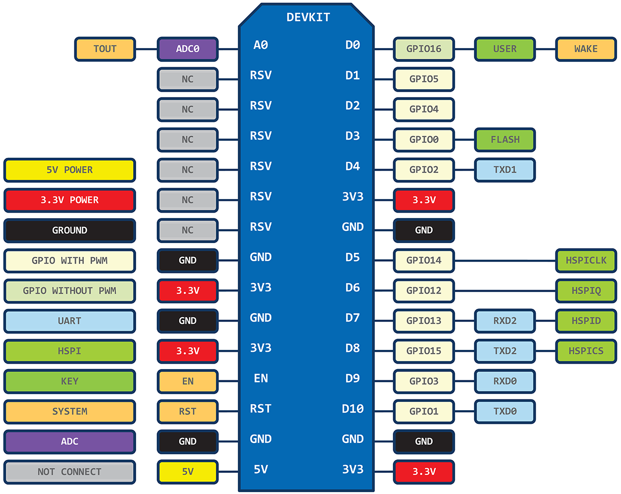
2nd generation / v1.0 / V2

The V2 fixes the short comings of the initial board, it’s more narrow and fits nicely into bread boards. The chip was upgraded from a ESP-12 to a ESP-12E.
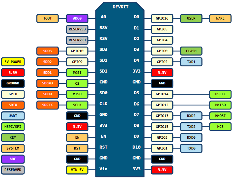
2nd generatopm ESP8266 NodeMCU development board
2nd generation ESP8266 NodeMCU development board

Pin layout of 2nd generation ESP8266 NodeMCU development board. Source: https://github.com/nodemcu/nodemcu-devkit-v1.0

V3

So, what’s with the V3? NodeMCU haven’t released a new specification so far. Hence, there’s no official 3rd generation board. Turns out that V3 is a “version” invented by producer LoLin to signify minor improvements to the V2 boards. Among others they claim their USB port to be more robust.

Pin layout LoLin NodeMCU development board V3. Source: http://www.wemos.cc/wiki/Hardware/Pin
If you you compare the pin layout there’s only a tiny difference to the V2 layout. LoLin decided to use one of the two reserve pins for USB power out and the other for an additional GND.
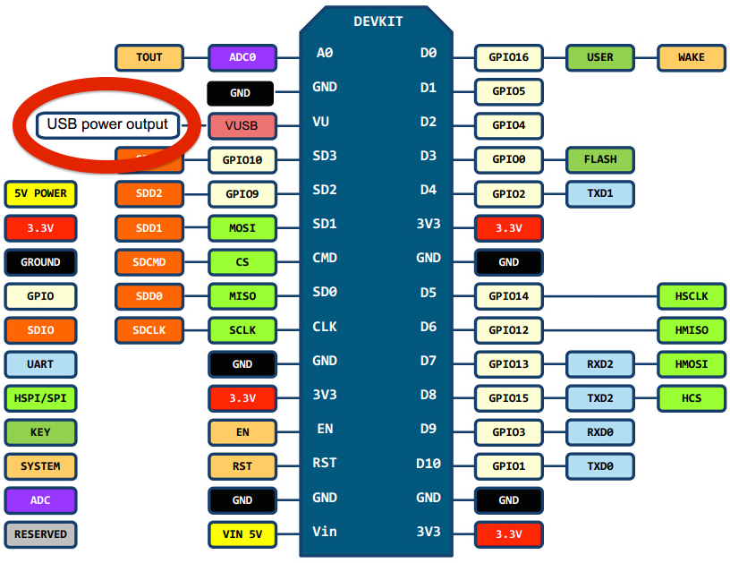
Watch out though for the difference in size! This LoLin board is significantly larger than the Amica and DOIT V2 boards. Because of its size I would never use it. There are clearly better alternatives.
AND what’s LoLin got to do with WeMos? I wish I knew…The pin layout you see here was originally hosted on wemos.cc but the link is now dead.
Relationship between NodeMCU and AmicaWhat’s the relationship between NodeMCU and Amica? Here’s what I know.
Many V2 boards are created by or at least labeled with ‘Amica’. It’s a brand name created by the Dutch Gerwin Janssen who seems to spend a lot of time in Shenzhen, China. He’s behind the NodeMCU Facebook account and owns the amica.io domain.
Although not officially part of the original NodeMCU team Gerwin designed a name for the devkit v1, called Amica. The team liked it and adopted the name.

Official vs Unofficial

NodeMCU posted a photo on Facebook which shows official and unofficial V2 boards. I don’t really understand the notion of official. It’s my understanding that with open-source hardware there’s no such thing as official boards. What it maybe means is that Amica is the “endorsed” producer and DOIT & LoLin are not.

official NodeMCU development board
Official NodeMCU 1.0/V2 development board
NodeMCU posted another photo on Facebook (see left) with specifics what is considered official and what not. Amica really seems to be the only producer which is 100% in-line with the V2 NodeMCU hardware spec. The Amica boards are not sold at Banggood but you can get them at AliExpress and seeed studio.

Alternatives

WeMos D1 mini

At the end of 2015 the hottest alternative seems to be the WeMos D1 mini. It has roughly the same width as a V2 NodeMCU devkit but at 34.2mm it is nearly a third shorter. It runs an ESP-8266EX MCU and provides 4MB flash. Its nine GPIO pins make the D1 mini suitable for a large IoT target audience. It supports both Arduino and NodeMCU.

WeMos D1 mini
WeMos D1 mini, a NodeMCU devkit alternative
WeMos also sells a number of shields of equal size which allows to build nicely stackable units.
The only downside for many may be that you have to solder the pins yourself. Each D1 mini comes with a pair of long and short female pins and a pair of normal pins. Some reports on the Internet claim that it can be a bit difficult to get proper drivers for the CH34x USB to serial chip on the D1 mini. That’s the same chip used by some of the cheap Arduino clones.
Also, it’s obviously got a few pins less than the NodeMCU boards, check the pin map. How else would they be able to reduce the length so much? On the other hand it’s also got a 5V out just like the LoLin V3.
Oh, and the best part? They’re sold at Aliexpress for just MYR 16.45 ( $4)! I ordered mine on December 19th and got them in the mail on the 31st, that’s impressive. They’re sent by registered(!) air mail.

WiFiMCU

DOIT/SmartArduino, producer of V2 boards, also has a dev kit alternative that uses a Cortex-M4 chip instead of the ESP8266 with otherwise the same board.

Adafruit/SparkFun


Adafruit HUZZAH ESP8266 Breakout
Among the others two that come to mind pretty quickly are the SparkFun ESP8266 Thing and the Adafruit HUZZAH ESP8266 Breakout. I don’t own either of them but the Adafruit board, as most of their stuff, looks pretty neat. It’s a bit smaller than the NodeMCU dev kits but you need a special USB to TTL serial cable rather than a standard USB cable.
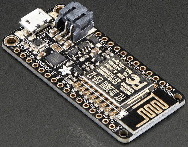
Recently I discovered Adafruit sells a development very similar to the NodeMCU v2 dev kit but with an additional LiPo connector – pretty cool. See the separate article for details.

Adafruit Feather HUZZAH with ESP8266 and LiPo connector

ESP8285 development board

In a separate article from June 2016 I’ll show you how to use the NodeMCU firmware on a tiny ESP8285 development board. That SoC is very similar to the ESP8266 except that it’s got 1MB SPI flash embedded right in the SoC.

ESP8285 development board
ESP8285 development board with FTDI FT230X USB-to-serial converter, a MAX1555 LiPo battery charger and 11 GPIO


26 thoughts on “Comparison of ESP8266 NodeMCU development boards”

  1. LoLin version looks like (from the photo in the link posted above) it uses CH340 as USB converter where instead Amica v.2 and DOIT v.3 (produced by smARtDUINO… =8-| …) use CP2102.
    1. My feeling as to why LoLin chose to call their product a “V3” instead of a “V2” is because they “missed the boat” when it came to reducing the width of their PCB, so folks comparing it to say an old Amica v0.9 board (which is just as wide as the LoLin board and is considered by most people as “breadboard unfriendly” because there is no free (available) pin hole in a MB-102 solderless breadboard when you mount these boards, well they had to do something to recover or gain market share so they call it V3. I have a couple of them and they seem to be pretty good boards. I usually breadboard then using a pair of mini breadboard (the kind w/o power rails and a 17 x 10 layour of pin holes). If you separate them by about 1.5cm, you can plug in the LoLin NodeMCU (or Amica v0.9) and it will fit pretty well. I generally then peal off the backing tape on the double sided tape that comes on back of these breadboards and plunk them down onto a wooden board using the NodeMCU as a space. This way you get a real stable work area.
  2. Thanks for digging up this information and laying it out clearly, you saved me a bunch of time researching these for myself, not to mention the frustration of almost ordering one of the oversized LoLin “V3” boards. With any luck, I have an Amico board on the way to go with the two DoIt boards I got from Bangood previously.
    Ok, now back to getting my ESP8266 based OneWire temperature server sketch complete and debugged…
  3. I also think that the latest nodemcu firmware 1.4.0 that you get when you use http://nodemcu-build.com/index.php, the great custom build website from frightanic has the pin mappings for the amica board correct, i.e. D1 is 1, D2 is 2 etc. Took me a while to figure out which software pin corresponded to which board pin
  4. Amica boards allow you to use DIO mode freeing up 2 more GPIO’s for on/off functionality the way in which they are wired is a mod version thus making them the most useful boards sold to date.
    Lolin board is my second favorite as it is cheap and the pin spacing seems to work fine with dupont connectors why breadboard when you can create cheap wiring harnesses to do the work with mostly every module out there. It is dupont harnessing or go home for me custom harnesses are relatively simplistic by nature and cheap and effective if only other people understood this principal … I think we may see more of an influx of testing and projects.
  5. Long before modified version of NodeMCU and Lolin or adafruit boards were available, smartWIFI was introduced (March-15) by KNEWRON (www.knewron.co.in). They had introduced battery charger and USB converter with power out, switch, RGB LED, user button on board which later inspired other guys to follow.
    Available on Tindie now: tindie.com/products/Knewron/smartwifi-development-module-esp8266-based/
  6. Hello.
    Just wanted to mention that Wemos’s D1 mini is not the same as their previous LoLin board which I have – D1 has quite a few pins less, specifically soft SPI and SDIO pins (SD0-3, SDCLK, SDCMD interleaved with MOSI, MISO, SCLK, CS and GPIO9/D11, GPIO10/D12).
    I suppose you knew about that, but I thought it needed to be explicitelly stated for those who thought, like I did, that D1 mini is just different form factor with two-sided components.
    Basically, an updated/shortened LoLin board…
    So, maybe you should emphasize that if you need those pins, one should not go for D1 mini but instead go for regular V2/V3 board.
    Cheers, Andrea
  7. YouTuber Andreas Spiess has a nice review of the various options for ESP8266, it is reasonabley recent (2016)
  8. Here’s another board to consider: Onion Omega (https://onion.io) is truly a board oriented towards IOT devices and projects! It’s super small, has built-in WiFi, runs Linux, program it using popular web languages (Node.js, Python, etc.), lots of Expansions (bluetooth, gps, servo, etc.) to extend the capabilities, can be remotely controlled/updated via Onion Cloud and very affordable!
  9. Thank you that’s a useful comparison.
    The CH340 is proving to be popular and drivers are much easier to find. The CH340 driver was incorporated into Chrome OS very recently and seems to be there by default in Ubuntu.
    The NodeMCU V2 seems to be the best value (I paid less than MYR 16.02 ( MYR 16.02 ( £3)) including P&P) and has all the features I want. The only drawback is that it’s pretty wide so it spans the breadboard completely. That’s not a disaster but it’s a bit annoying having to run jumpers underneath the board to connect it to anything.
  10. On the LoLin “v3” board – IMPORTANT! The usb connector is only soldered by the pins. The legs are inadequately soldered, if at all. Have two – same on each.
    Make sure to solder the four legs to stabilize the connector. Solder can be applied from back with a hotter fine tipped iron.
    I spent hours of frustration, changing cables, using different software, baud rates, and cursing different parts of the universe, before I noticed that the USB connector was not secure.
  11. @cc young thanks for the heads up, have one coming for the ‘collection’, will be switching to ESP8266-100 and ESP8285 with our lipo charger while waiting on the ESP32..

Leave a Reply

Your email address will not be published. Required fields are marked *

:)

Monday 19 September 2016

Arduino goes STM32 ARM


original 

Arduino goes STM32


You can develop for STM32 using the Arduino IDE. Here are the steps:
What you need:
  • STM32F103C8T6 module (ARM32 Cortex-M3, 72 Mhz, 64K flash, 20K SRAM, 33 I/O pins, 3.3V), you can find cheap modules on eBay
  • Serial-to-USB-module (3.3V level, e.g. CH340)
Steps:
1. Wire STM32 module and Serial-to-USB module as shown below:

      
2. Download and install Arduino IDE (I did use 1.6.3)
3. Download ‘https://github.com/rogerclarkmelbourne/Arduino_STM32‘, extract it and copy the folder ‘Arduino_STM32-master’ to your Arduino/hardware folder (C:\Programs\Arduino\hardware).
4. Run Arduino IDE, choose settings:
Board: Generic STM32F103C series
‘Variant: STM32F103C8 (20k RAM, 64k Flash)’
Upload method: Serial
‘Port: <the COM port of your USB-to-serial adapter>’
5. Compile this sketch:
#define pinLED PC13

void setup() {
  Serial.begin(9600);
  pinMode(pinLED, OUTPUT);
  Serial.println("START");  
}

void loop() {
  digitalWrite(pinLED, HIGH);
  delay(1000);
  digitalWrite(pinLED, LOW);
  Serial.println("Hello World");  
}
6. On the board, set ‘BOOT0‘ to 1 (will boot from system memory which contains an UART to flash uploader). Press RESET button.
7. In the Arduino IDE, choose ‘Upload‘. On the board, the blue LED will start to flash.
8. After upload completed, your sketch will start. If you want your uploaded sketch to boot automatically after next power-on/reset, set ‘BOOT0‘ back to 0 (will boot from program memory). Press RESET button.
Arduino demo code for STM32F103C8T6:
1. SPI interface
#include "SPI.h"

#define pinLED PC13
#define pinRST PB0
#define pinIRQ PB1

#define pinSPI_SS  PA4  
#define pinSPI_CLK PA5
#define pinSPI_MISO PA6
#define pinSPI_MOSI PA7

volatile int irqCounter = 0;
int lastIrqCounter = 0;

void handleIRQ(){
  irqCounter++;
}

void setup(){  
  pinMode(pinLED, OUTPUT);
  pinMode(pinSPI_SS, OUTPUT);
  pinMode(pinRST, OUTPUT);
  pinMode(pinIRQ, INPUT);  

  Serial.begin(115200);
  Serial.println("START");
  attachInterrupt(pinIRQ, handleIRQ, RISING);

  // Initializes the SPI bus by setting SCK, MOSI, and SS to outputs, pulling SCK and MOSI low, and SS high. 
  SPI.begin();  

  digitalWrite(pinRST, LOW);
  delay(200);
  digitalWrite(pinRST, HIGH);
  delay(100);
}

void spiTest(){
  unsigned long msg = 0;
  SPI.beginTransaction(SPISettings(16000000L, MSBFIRST, SPI_MODE0));
  digitalWrite(pinSPI_SS, LOW);
  SPI.transfer(0x00);
  msg = SPI.transfer(0x00);
  msg = (msg << 8) + SPI.transfer(0x00);
  msg = (msg << 8) + SPI.transfer(0x00);
  msg = (msg << 8) + SPI.transfer(0x00);  
  digitalWrite(pinSPI_SS, HIGH);
  SPI.endTransaction();  
  Serial.println(msg, HEX);  
}

void loop(){
  digitalWrite(pinLED, HIGH);
  delay(100);
  digitalWrite(pinLED, LOW);
  delay(100);  
  if (irqCounter != lastIrqCounter){
    Serial.println(irqCounter);
    lastIrqCounter = irqCounter;
  } 
  spiTest();
  delay(2000);
}
2. I2C interface:
#include <Wire.h>

#define OLED_address  0x3C

int pinSDA = PB4;
int pinSCL = PB5;

TwoWire MyWire(pinSCL, pinSDA);

MyWire.beginTransmission(OLED_address); //start transmission to device 
MyWire.write(0x80);        // send register address
MyWire.write(0);        // send value to write
MyWire.endTransmission(); //end transmission


3.

Arduino vs. Raspberry Pi

There are some misconceptions here. Arduino is able to do all the things that a Linux machine can do, even faster. Provided the software is not complex. Software such as Matlab. Arduino can have access to web sites easily.

Original

Arduino vs. Raspberry Pi: Mortal enemies, or best friends?


In the DIY maker community, there’s no shortage of options designed to provide you with a little electronic control over your projects. Two of the most popular options for doing so are the budget-friendly Raspberry Pi, a system-on-a-chip (SoC) that runs a full version of Linux and was designed with teaching in mind, and the Arduino, a micro-controller with a large community of support and hundreds of expansion chips (aka shields).
However, while the initial announcement of the Raspberry Pi may have led many to proclaim the Arduino obsolete, such a declaration might be premature. The fact is, the two devices have different uses and advantages, each of which is achieved through different methods. The stark specification differences between the two also renders direct comparisons somewhat moot on paper, especially considering the Arduino’s 16MHz processor falls a little short of the Pi’s 900 MHz chip.
Related: Get under the crust of these 10 fun and easy Raspberry Pi projects

Raspberry Pi

RaspberryPi2For all intents and purposes, the Raspberry Pi is a fully functional computer. It has all the trappings of a computer, with a dedicated processor, memory, and a graphics driver for output through HDMI. It even runs a specially designed version of the Linux operating system. That makes it easy to install most Linux software, and lets you use the Pi as a functioning media streamer or video game emulator with a bit of effort.
Though the Pi doesn’t offer internal storage, you can use SD cards as the flash memory for the entire system, allowing you to quickly swap out different versions of the operating system or software updates to debug. Because of the device’s independent network connectivity, you can also set it up for access via SSH, or transfer files to it using FTP.

Arduino

ArduinoArduino boards are micro-controllers, not full computers. They don’t run a full operating system, but simply execute written code as their firmware interprets it. You lose access to the basic tools an operating system provides, but on the other hand, directly executing simple code is easier, and is accomplished with no operating system overhead.
The main purpose of the Arduino board is to interface with sensors and devices, so it’s great for hardware projects in which you simply want things to respond to various sensor readings and manual input. That might not seem like a lot, but it’s actually a very sophisticated system that allows you to better manage your devices. It’s great for interfacing with other devices and actuators, where a full operating system would be overkill for handling simple read and response actions.
Related: Arduino lets plants water themselves

Power

The two systems have very different power requirements. The Raspberry Pi requires constant 5V power to stay on, and moreover, should be shut down via a software process like a traditional computer. Arduino, on the other hand, begins executing code when turned on and stops when you pull the plug. To add functionality, you either wire directly into the pins on the Arduino board or stack chips called “shields” on top of the base unit. There are hundreds of shields, each of which is designed to perform a different task, interface with certain sensors, and work with one another to build a complete control unit.
Portability is an issue with the Pi, given it requires more than simply plugging in a couple AA batteries. The device requires you to set up a power supply and some additional hardware in order to provide it with the constant power needed. The process is a bit simpler on the Arduino, as you merely need a battery pack that keeps the voltage above a certain level, along with a basic shield to manage the power. Even if the power drops on the Arduino, you won’t end up with a corrupt operating system or other software errors. It will just start running code when it’s plugged back in.

Networking

The Pi has a built-in Ethernet port, which allows easy access to any network with little setup. Wireless Internet on the Pi isn’t hard to achieve either, you just have to buy a USB Wi-Fi dongle and install a driver. Once you’re connected, you can use the OS to connect to Web servers, process HTML, or post to the Internet. You can even use it as a VPN or print server.Ethernet port pc connection
Unfortunately, the Arduino isn’t built for network connectivity directly out of the box. It requires a bit more tinkering to set up a proper connection, though it is possible. You’ll need an extra chip outfitted with an Ethernet port, and you’ll need to do some wiring and coding in order to get everything up and running — which is enough of a process that some vendors sell comparable versions of the Arduino with built-in Ethernet.
Related: When is Wi-Fi better than Ethernet?

Sensors

While both the Pi and Arduino have a number of interface ports, it’s much easier to connect analog sensors to the Arduino. The microcontroller can easily interpret and respond to a wide range of sensor data using the code you put on it, which makes it great if you intend to repeat a series of commands or respond to sensor data as a means of making adjustments to servos and devices.
The Pi, on the other hand, requires software to effectively interface with these sorts of devices, which isn’t always what you need if you’re just trying to water plants or keep your beer at the right temperature. It’s not uncommon to use both in a project, with the Arduino acting as a control board that executes commands issued by the Pi’s software, before the sensor information is fed back for recording or responding to.

Match made

So which one is right for you? There isn’t a clear answer, because it depends heavily on your project.
When should you choose Arduino? When the main task is reading sensor data and changing values on motors or other devices. Given the Arduino’s low power requirements and upkeep, it’s also a good choice if your device will be constantly running and requires little to no interaction.
When should you go with Raspberry Pi? When you would otherwise complete your task with a personal computer. The Pi makes a slew of operations easier to manage, whether you intend to connect to the Internet to read and write data, view media of any kind, or connect to an external display.
Given the two devices accomplish different tasks, it’s best to use both in some instances. There are a number of options for connecting the two devices, which will give you client-side access to the settings and code via the Pi, while the Arduino handles the actuation of devices and gathers data from the sensors. There are a number of ways to go about making the connection, whether you prefer USB, a local network, or by running some of the IO ports on the Arduino into the Pi.

Monday 12 September 2016

The cheapest and best USB to Serial converter

The cheapest and best USB to Serial converter module for microprocessors with Arduino IDE.10 p
Buy 10pcs  for RM32 to get the best price sent via registered post, which is faster and more reliable.
It can work with both 5V and 3.3V Arduino modules.

10-pcs-USB-to-TTL-UART-Module-CH340G-STC-Microcontroller-Download-Cable-Brush-Board-USB-to

10 pcs USB to TTL UART Module CH340G CH340 STC Microcontroller Download Cable Brush Board USB to Serial 3.3V 5V Switch

Rated 5.0/5 based on 48 customer reviews 5.0 (48 votes)
42 orders
Price:
US $7.99 / lot
10 pieces / lot , US $0.80 / piece
Shipping:
Estimated Delivery Time:22-38days
Quantity:
lot (891 lots available)
Total Price:
US $7.99
Store Promotion:
Get a US $2.00 coupon
Return Policy:
Returns accepted if product not as described, buyer pays return shipping fee; or keep the product & agree refund with seller. View details
Seller Guarantees:
Payment:

Buyer Protection

  • Full Refund if you don't receive your order
  • Full or Partial Refund , if the item is not as described
Report item
Item specifics
  • is_customized: Yes
  • Type: Voltage Regulator
  • Model Number: USB to TTL UART Module CH340G CH340 STC Microcontroller
  • Condition: New
  • type1: UART Module
  • type2: Microcontroller
  • type3: USB to TTL
Product Description
USB to TTL UART Module CH340G CH340 STC Microcontroller Download Cable Brush Board USB to Serial 3.3V 5V Switch
 
 
Feature:
Status LED.
Built-in USB to TTL Transfer chip.
Used for USB to TTL electronic projects.
TTL interface output, easy to connect to your MCU.
Dual 3.3V and 5V Power output, work with 3.3v and 5v target device.
Size:55mm * 16mm
 
1. support WINDOWS 98/ME/2000/XP/Server 2003/VISTA/Server 2008/Win7/Win8 32 bits & 64 bits.
2. 3.3V and 5V by a short circuit risk selection;
3. not only has the power light PWR, there TXD and RXD indicator, whether the product is easy to learn and intuitive to work in the absence of the instrument in the case;
4. high-quality high-grade yellow pin, pin durable than the black market, beautiful;
5. new original CH340G chips, the chips are recommended STC official USB to TTL chips will not appear due to different driver / different computer as a result of incompatibilities!
 

Friday 9 September 2016

Success with Ov7670 Camera with Arduino Nano

I have successfully installed the Ov7670 camera with the Aruino Nano to output the picture to a PC via a java frame grabber as described in the tutorials which are reproduced in the last few posts. When you run the eclipse IDE, there is an error which requires us to create a new folder at c:\new, which is hard coded into to java code of the frame grabber.

Make sure you install the java comm library as shown by this tutorial:
how-to-install-java-communications.html

There is no installer for my version of eclipse juno IDE for windows 32-bit.


350 lines per vertical.


Accidentally taken, handheld.
Do not use the battery. It created lots of noice. For standalone, need to install more decoupling capacitors across the power bus.
Create a runable jar file using this menu. Execute using: java -jar filename.jar

Thursday 8 September 2016

Success story of OV7670 without FIFO

OV7670-Without-FIFO-Very-Simple-Framecapture-With

I had finished installing them and managed to get some data on the Ardduino serial monitor but still cannot run the java frame grabber. It is included here but my com port is 6. What is provided is only com port 1-5.

OV7670 without FIFO very simple framecapture with Arduino, black/white

by in technologyarduino
Picture of OV7670 without FIFO very simple framecapture with Arduino, black/white
This instructable is for all the people struggling to just take a picture/grab a frame with their OV7670 without FIFO. I made this purely as an introduction. I do not yet posses the necessary coding skills to make a really great description. This was made to hopefully save some people a lot of the hours I used researching the OV7670 wanting to see if it worked.
All the coding provided is copied from these links:
http://forum.arduino.cc/index.php?topic=159557.0 (From a really cool guy but obviously not a fan of the arduino IDE or windows)
http://embeddedprogrammer.blogspot.dk/2012/07/hack... (Provides a lot of usefull information for understanding how the OV7670 works)
http://privateblog.info/arduino-uno-i-kamera-ov767... (is in russian, but with google translate you can actually extract some useful information)
Other useful documents are captured in the rar file.

Step 1: Identify your camera

Picture of Identify your camera
This might be a little redundant but before you get down to the nitty-gritty make sure that the camera you bought is the one without FIFO. I bought mine from http://www.dx.com/p/jtron-ov7670-300kp-vga-camera-.... If your pins mention fifo or you do not have 18 pins for exits this is not the tutorial for you! Btw, if you are thinking about buying the OV7670 and you don't do coding let me save you some time. Spend a more little money and go for one that is better supported by the community for non-coders.

Advertisement

Step 2: Connecting the pieces

Picture of Connecting the pieces
Table.PNG
The OV7670 is not rated for voltages above 3.0v. Hence the voltage divider for the XCLK. Futhermore the OV7670 does not provide higher voltages than 3.0 which is a little low to be sure the arduino reads the input as high (it starts at 3.0v). Therefore we connect pull-up resistors.

Step 3: Upload sketch to Arduino

The sketch is borrowed from this link:
https://github.com/ComputerNerd/ov7670-no-ram-ardu...
and put together in the ino file I uploaded (From_Computernerd).
Just insert the ino file in the Arduino IDE and upload it. Don't mind that it does not recognize some libraries in the beginning of the file. If it bothers you, comment the whole line out with //

Step 4: Different option to "grab" picture

If you only care about making the OV7670 work, proceed to the next step.
This is just to inform people of some of the different options to retrieve the pictures from the Arduino. I tried using the framegrabber from ComputerNerd:
https://github.com/ComputerNerd/simpleFrameGrabber
It seems to be written in UNIX/Linux. Hence I tried downloading the MinGW, which should be able to run the code. After adding several packages in MinGW I had to stop because MinGW does not contain the termios.h library which is used in the code.
Another option to run GNU in windows is Cygwin. In Cygwin you also install packages with different libraries. I tried running the code installing new packages whenever Cygwin told me a library was missing. In the end I was able to compile an exe file but it wouldn't run because allegedly cygjpeg-8.dll and cygSDL-1-2-0.dll was missing even though I had installed both packages.
Finally abandoning all hope of running the "original" framegrabber I found a russian website where a guy had made his own framegrabber in java instead.

Step 5: 1. half.

Picture of 1. half.
Change port.png
-Create a new folder on your c drive called out, like c:\out. This is where the pictures will end up.
-Download and install java SDK 32bit (don't install the 64 bit version even if your system is 64 bit) I've tested this with version 8u74.(I've included it as a rar-file because it wouldn't let me upload the exe-file)
-Find out what USB port your Arduino is connected to, something like COM3 or COM4. Check pictures to understand how.
-Depending on what port number your Arduino is connected to, download the corresponding file: COM1 = com_1.rar etc.

Step 6: 2. half.

Picture of 2. half.
cmdfinal.png
-Go to the "bin" folder, where you installed the Java SDK. By default it should be C:\Program Files (x86)\Java\jdk1.8.0_74\bin.
-Unpack your corresponding com_#.rar files in the directory. Check picture for help. (it might ask for adm. permission)
test44.bmp
-Download and extract the Extra.rar file. The "win32com.dll" is placed in the "...\jdk1.8.0_74\jre\bin" direktory.
the "comm.jar" in "...\jdk1.8.0_74\jre\lib\ext" and the "javax.comm.properties" in the "...\jdk1.8.0_74\jre\lib" directory.
-Open cmd
-Open the folder wherein the code is (mine is): cd C:\Program Files (x86)\Java\jdk1.8.0_74\bin
Write: java code.SimpleRead
Enjoy! (It isn't much but at least you got it working)

Step 7: Troubleshooting and pictures

Picture of Troubleshooting and pictures
1.bmp
2.bmp
test37.bmp


-If your cmd does not "FIND" images try switching the USB of the arduino from a USB2.0 to a USB3.0 (blue socket) or vice versa.
-If your cmd does not "FIND" images or if you recieve SCRAMBLED pictures, you need to edit the ino file. Edit the line: wrReg(0x11, 12);
try changng the 12 to 11 or 10 or 9 or 13. Upload it to the arduino and run the cmd code again.
Good luck!