
Esp32 Cam Surveillance Car
Esp32 Cam Surveillance Car
Hardware components | ||||||
 |
| × | 1 | |||
 |
| × | 1 | |||
Software apps and online services | ||||||
 |
| |||||
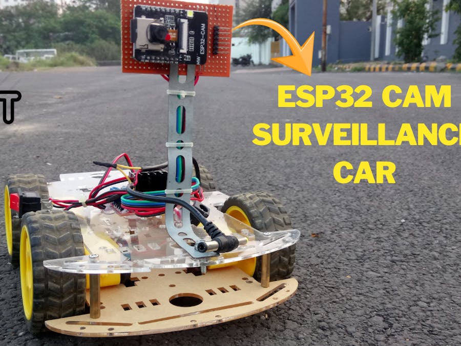
this time we are attaching a camera with the robot to make it a surveillance robot car. This web controlled surveillance car can be easily built using the ESP32-CAM module. Apart from the ESP32-Camera module, here we will use two DC motor with Robot chassis and L293D motor driver module to build this Robotic car. ESP32 is one of the most popular boards to build IoT based projects
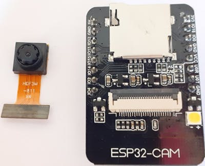
The AI-Thinker ESP32-CAM module comes with an ESP32-S chip, a very small size OV2640 camera and a microSD card slot. MicroSD card slot can be used to store images taken from the camera. Here HTTP communication protocol will be used to receive video streaming from the OV2640 camera over the web browser. The web page will also have buttons to move the car in Left, Right, Forward and reverse directions as shown in the image above.
Components Required- ESP32-CAM
- L
- DC Motors (2)C Motors (2)
- Motor Driver (L293D)
- Battery
Also, download and install the Arduino IDE to upload the into ESP32.
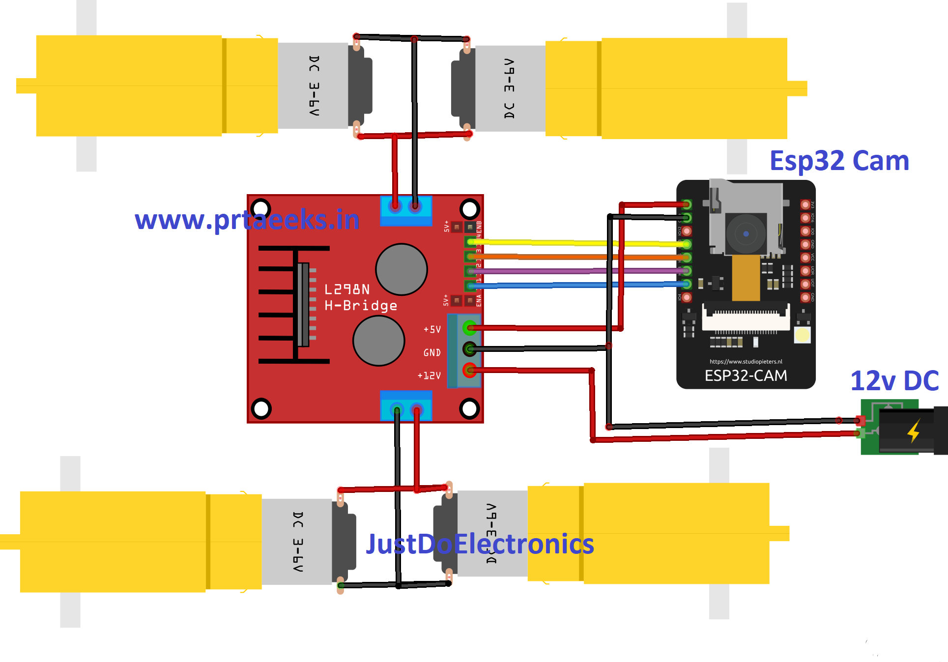
Circuit DiagramAll the connections for ESP32- Surveillance Camera is given below:
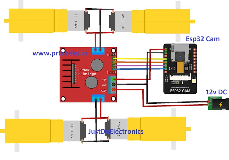
ESP32-CAM doesn’t have a USB connector, so you need an FTDI board to upload the code into ESP32-CAM. VCC and GND pin of ESP32 is connected with the VCC and GND pin of the FTDI board. Tx of and Rx of ESP32 is connected with Rx and Tx of the FTDI board. Two DC motors are connected to ESP32 through the L293D module. Module pins are connected to IO4, IO2, IO14, and IO15 pins of ESP32.
Note: Before uploading the code, connect the IO0 to the ground. IO0 determines whether the ESP32 is in flashing mode or not. When GPIO 0 is connected to GND, the ESP32 is in flashing mode.
We built a robot by using a ready-made robot chassis, wheels, and DC motors. We used a battery to power the motor drive module and ESP32-CAM. This is how my surveillance robot looks like:
_ukh0Y7SVid.png?auto=compress%2Cformat&w=740&h=555&fit=max)
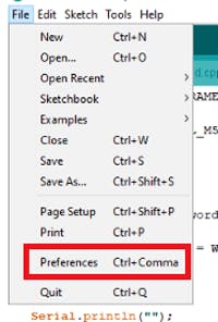
We will program the ESP32-CAM using Arduino IDE. For that, we have to install the ESP32 add-on on Arduino IDE.
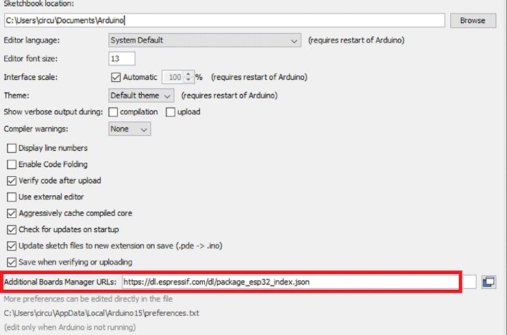
To install the ESP32 board in your Arduino IDE, go to File> Preferences
Now copy the below link and paste it into the “Additional Board Manager URLs” field, as shown in the image below. Then, click the “OK” button:
https://dl.espressif.com/dl/package_esp32_index.json
Now go to Tools > Board > Boards Manager
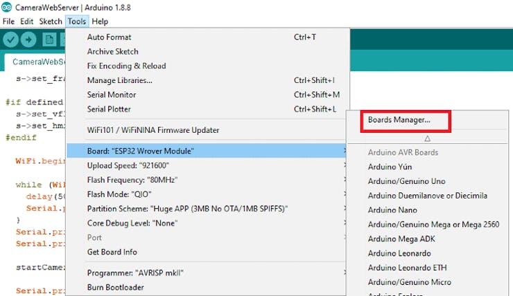
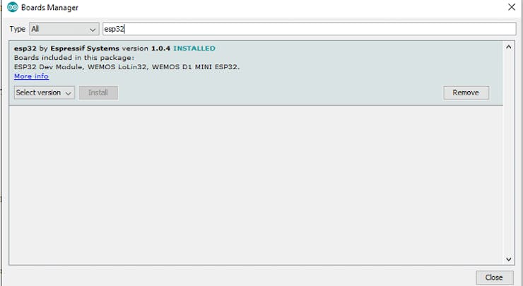
In Boards Manager search for ESP32 and install the “ESP32 by Espressif Systems“.
This ESP32 Surveillance Camera has a total of four code files that are attached at the end of the project and also can be downloaded from here. One is the main code file for camera and motors, and the other three codes are for web page, camera index, and camera pins.
Begin the program by including header files and selecting the right camera model. In the code, three camera models are defined. Uncomment the camera model that you are using. Here we have used the AI Thinker camera model that comes with ESP32.
#include "esp_camera.h"
#include <WiFi.h>
#include "camera_pins.h"
// Select camera model
//#define CAMERA_MODEL_WROVER_KIT
//#define CAMERA_MODEL_M5STACK_PSRAM
#define CAMERA_MODEL_AI_THINKER
Enter the Wi-Fi name and password of the network.
const char* ssid = "WiFi Name";
const char* password = "Password";
The four pins 4, 2, 14, and 15 of the ESP32 are used to control the DC motors.
extern int leftmotor1 =  4;
extern int leftmotor2 = 2;
extern int rightmotor1 = 14;
extern int rightmotor2 = 15;
Inside the void setup loop, begin the serial monitor and set the DC motors initially low.
void setup() {
  Serial.begin(115200);
  Serial.setDebugOutput(true);
  Serial.println();
  digitalWrite(leftmotor1, LOW);
  digitalWrite(leftmotor2, LOW);
  digitalWrite(rightmotor1, LOW);
  digitalWrite(rightmotor2, LOW)
Define the Pins of DC motors as Output.
pinMode(leftmotor1, OUTPUT);
pinMode(leftmotor2, OUTPUT);
pinMode(rightmotor1, OUTPUT);
pinMode(rightmotor2, OUTPUT);
Connect to the Wi-Fi using the given credentials and wait for the confirmation
WiFi.begin(ssid, password);
 while (WiFi.status() != WL_CONNECTED) {
    delay(500);
    Serial.print(".");
  }
  Serial.println("");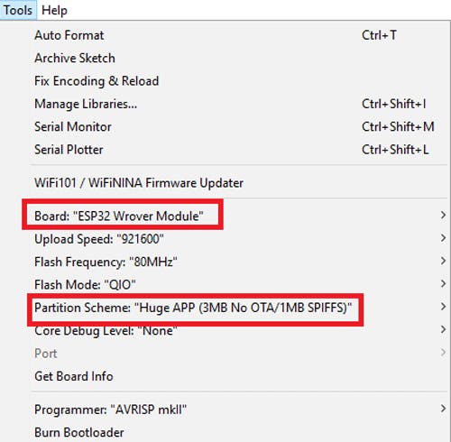
Serial.println("WiFi connected");To upload the code, connect the FDTI board to your laptop and select the ‘ESP32 Wrover Module’ as your board. Also, change the other settings according to this picture:
Before uploading the code, press the ESP32 reset button and then click on the upload button.
Note: If you get errors while uploading the code, check that IO0 is connected to GND, and you have selected the right settings in the Tools menu.
After uploading the code, disconnect the IO0 and GND pin. Then open the serial monitor and change the baud rate to 115200. After that press the ESP32 reset button, it will print the ESP IP address and port no on the serial monitor.
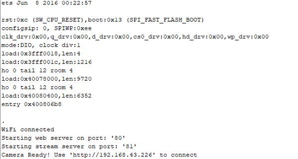
Now to access the Webpage for ESP32 video streaming and car controls, navigate to your browser and enter the ESP IP address. It will take you to the web page.
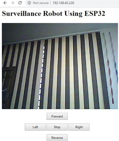
From here, you can control the car using the control buttons while receiving video streaming from a web browser.
This is how you can make a surveillance robot using ESP32-CAM. Complete code and demonstration video is given below. Code folder has four codes in which the first code is for ESP32 and peripherals connected to ESP32; the second code is for the HTML web page, the third code is for camera index, and the fourth code is for camera pins.
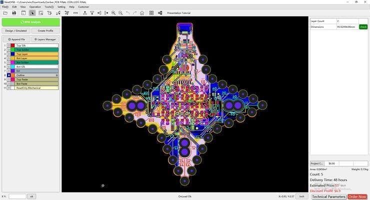
PCB Design Analysis Software. NextDFM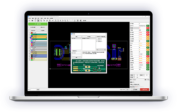
Nextdfm Software
NextDFM is a PCB problem detector and engineering tool by NextPCB, one of the most professional PCB manufacturers in the world based in China. NextDFM is a simple software which can be learnt easily by a non regular PCB designer also. The UI created by them is very simple and PCB design analysis can be done in just a few clicks.
Help you quickly familiarize DFM design specifications and production needs to determine whether there are any manufacturing constraints


Comments
Please log in or sign up to comment.